Fibre optic links are a clear choice for many high-speed, long-distance network connections. They carry optical signals rather than electrical Ethernet signals through the cable, supporting everything from building links to internet backbones. Choosing a working link, however, means matching the cable, connectors, transceivers and equipment rather than simply buying a yellow or aqua patch lead.
Copper remains valuable for short connections and devices that need power over the same Ethernet cable. The useful comparison is the complete link at the speed and distance you require, including installation, ports, modules and maintenance.
How Fibre Carries Data
An optical transmitter converts data into modulated light, the fibre guides that light, and a receiver converts the signal back into electrical data. The core and surrounding cladding have different refractive properties that support guidance. The Fiber Optic Association's explanation describes the material, modes and sources involved.
Light travels more slowly in glass than in a vacuum. Propagation speed is also different from data rate: a 10 Gbps link does not operate at 10 Gbps because its photons move faster than those in a 1 Gbps link. Modulation, optical characteristics and the transmitting/receiving equipment determine how much information the system can carry.
Real fibres have attenuation, and optical pulses can spread through dispersion. Connectors and splices add loss or reflections. Long distance does not mean no degradation; the complete path must remain within the chosen optics' supported reach and optical budget.
Copper Versus Fibre
| Consideration | Copper | Fibre |
|---|---|---|
| Link speed | Determined by the Ethernet interfaces, cable category, length and installation. | Determined by the optics, fibre type, length and installation. |
| Distance | Useful for short structured-cabling and rack links, within the relevant interface specifications. | Options extend from short rack links to long-distance systems, using appropriately matched optics. |
| Electrical interference | Balanced signalling, construction and correct installation help manage interference. | The optical signal is not affected by electromagnetic interference in the same way. |
| Power delivery | Supported twisted-pair Ethernet can supply Power over Ethernet to compatible equipment. | A normal optical data fibre does not supply PoE; the remote equipment needs power separately. |
| Practical cost | May use existing RJ45 ports and installed cabling. | May need transceivers, suitable ports, termination, inspection and testing. |
Neither medium is universally cheaper or faster. A short copper direct-attach cable can be sensible between compatible rack ports, while an optical link may suit a longer run or a noisy environment. Compare the total installed solution, not just the price of the cable.
Copper Cable Types and Categories
Twisted pair and coaxial cable are different constructions. Ethernet category labels such as Cat5e, Cat6 or Cat6A describe specifications for particular twisted-pair cabling systems; “Ethernet cable” is not a third construction separate from twisted pair. Coaxial cable has a central conductor, insulation and surrounding shielding and is common in cable-TV/broadband systems.
Shielding is useful when the whole installation is designed for it, including suitable connectors and grounding. Unshielded twisted pair is not automatically unreliable: its balanced signalling and twists are part of its interference performance.
Cat7 is not the highest category that exists, nor does a higher printed number automatically improve a connection. Fluke's cabling guidance distinguishes Cat5e, Cat6A and Cat8 among other classes and supported applications. Choose a documented cable system for the interface and distance instead of treating the category as a speed selector. A 1 Gbps port remains a 1 Gbps port with a more expensive cable.
Single-Mode, Multimode and Plastic Fibre
Single-mode fibre has a small glass core and supports one propagation mode for its intended operating conditions. It is widely used with laser sources for longer links, but can also be useful over short distances when matched to appropriate optics.
Multimode fibre has a larger core, commonly 50 or 62.5 micrometres, supporting multiple modes. It is common in premises and data centres. Older slower systems used LEDs, but modern high-speed multimode Ethernet commonly uses laser sources such as VCSELs. “Multimode means LED only” is inaccurate.
Plastic optical fibre is a separate family used in suitable short-range applications. Do not substitute it for a glass Ethernet patch cable because both are optical: core size, connectors, sources and the supported application differ.
Grades and Jacket Colours
Colours are useful clues, but the printed classification and manufacturer's specification are decisive. The FOA colour guide documents exceptions, customer choices and outdoor jackets; colour alone cannot prove a maximum Ethernet speed or distance.
| Classification | Typical identification | What to check |
|---|---|---|
| OM1 | 62.5/125 micrometre multimode, often orange. | Legacy core size and the chosen module's supported reach. |
| OM2 | 50/125 micrometre multimode, often orange. | Not interchangeable with OM1 merely because the jacket colour matches. |
| OM3 and OM4 | Laser-optimised 50/125 micrometre multimode, commonly aqua. | The exact printed grade and optical interface; some manufacturers use other identifying colours. |
| OM5 | Wideband 50/125 micrometre multimode, commonly lime green. | Benefit depends on the optical system; not automatically longer reach with every module. |
| OS1/OS1a/OS2 | Single-mode classifications, commonly yellow. | The actual cable specification and loss characteristics, rather than yellow meaning OS2. |
Reach Belongs to a Link Specification
For a concrete example, Cisco's 10G SFP+ data sheet lists these module/fibre combinations:
| Example | Medium | Advertised supported reach |
|---|---|---|
| SFP-10G-SR | OM3 multimode | Up to 300 m |
| SFP-10G-SR | OM4 multimode | Up to 400 m |
| SFP-10G-LR | Specified G.652 single-mode | Up to 10 km |
These figures apply to those documented links, not every cable of the same colour. A 40G, 100G or wavelength-multiplexed interface may have a different fibre count, connector and reach. Include all connectors and splices when checking allowable path loss. Long-reach optics may also specify a receiver maximum or require attenuation on short paths; consult their exact data sheet.
Connector Shape, Polish and Polarity
SC uses a push-pull connection, while compact LC is common on dense network optics. ST uses a bayonet-style connection and FC a threaded one; they remain relevant on installed systems. MPO provides multi-fibre connections, with MTP a familiar brand name for an MPO connector design. The FOA termination guide describes their construction and application.
Match more than the physical shape. Confirm fibre mode, connector polish, polarity and the interface's strand arrangement. A conventional duplex link needs transmit and receive connected correctly; a bidirectional single-fibre pair needs complementary optics. MPO systems also require the correct fibre arrangement and connector configuration.
UPC and APC Must Match at Each Mating Point
UPC is a non-angled physical-contact finish with a slightly rounded end face, not a completely flat tip. APC uses an angled finish, commonly eight degrees. Blue and green are common single-mode UPC and APC identifiers respectively, but verify the connector specification.
Fluke explains that directly mating UPC and APC creates poor alignment/reflection performance and can damage end faces. Avoid that mismatch; do not assume a fixed loss figure or that every incorrect connection produces identical permanent damage.
A correctly specified hybrid patch cord can have UPC at one end and APC at the other, because each end mates to the corresponding equipment finish. This is different from mating an APC plug directly to a UPC connector. Check the ONT or optical module's specification rather than assume every ISP connection uses the same polish.
Choose, Install and Verify the Complete Link
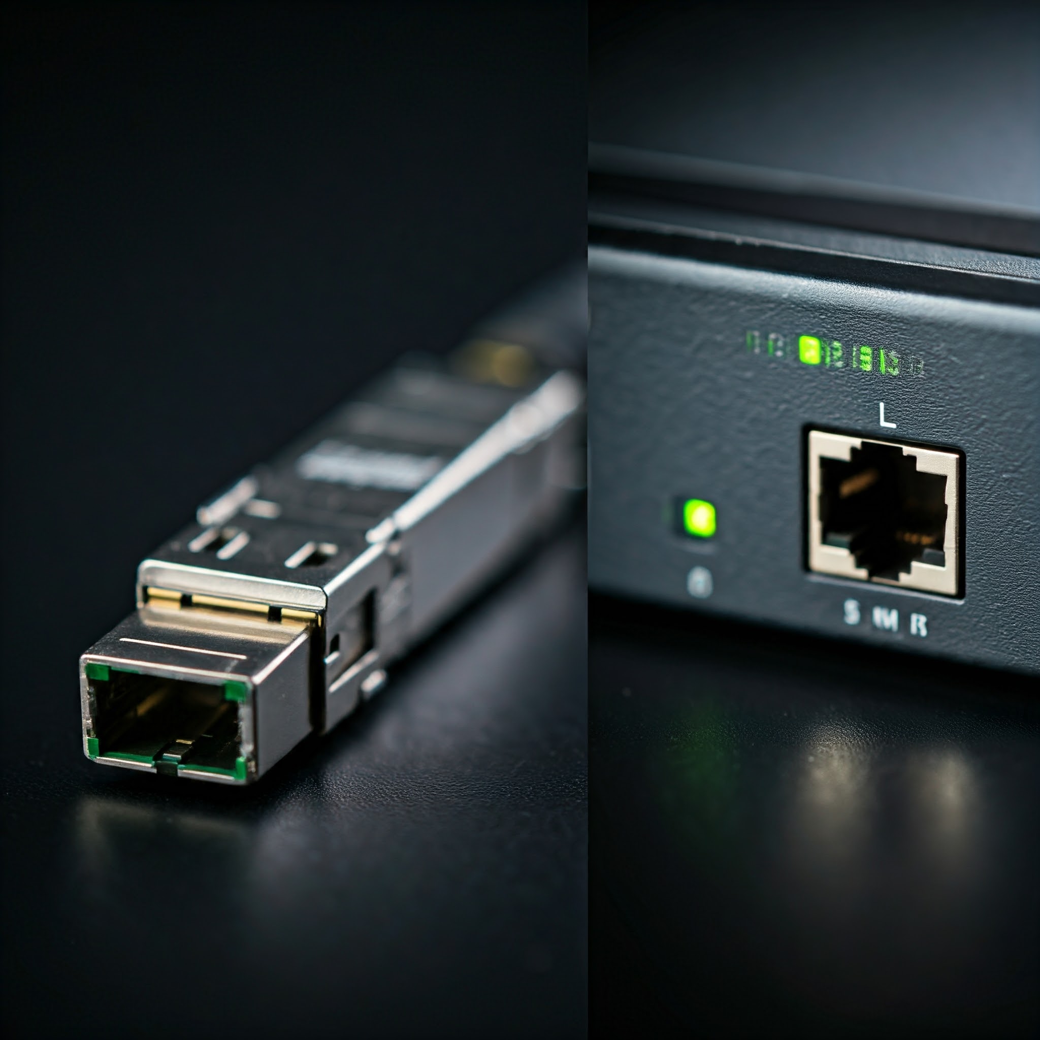
A removable SFP-family module is common, but not every optical port uses one and not every physically fitting module is supported. Copper RJ45 modules are separate electrical interfaces in a supported module form factor; they do not make an ordinary fibre cable carry copper Ethernet. See our in-depth article on SFP Ports for the port side of the decision.
- Record the devices, port types, required speed, cable route and total length.
- Select supported optics at both ends with matching Ethernet interface, wavelength/fibre requirements and suitable reach.
- Specify the patch leads and installed cable, including connector finish, strand count and polarity.
- Follow the cable's bend-radius and pulling limits. FOA's installation guidance emphasises manufacturer-specific limits and avoiding crushing or tight ties.
- Keep connector end faces clean, use appropriate inspection/cleaning tools and protect disconnected ends. Never look into a potentially active fibre or optical port; verify that optical power is absent before inspection.
- Confirm link speed and error counters, then test the actual transfer workload. Use appropriate optical testing for an installed cable plant; a link light alone does not certify all required loss margins.
Conclusion
Fibre remains an excellent choice for high-speed and long-distance connectivity. Its value comes from a correctly designed optical link, with matched components and a maintained cable path. Copper can still be the practical answer for short runs and powered endpoints. Use the interface requirements and installation evidence to choose a dependable link with a sensible upgrade path.